
The new FETs arrived from Hong Kong. It had taken only two and a half weeks which was not too bad. I installed them and then very carefully started to setup the bias. I had sweaty hands, but I managed to tweak the potentiometers so that each FET had quarter of an amp of bias current. I hard wired the RF deck to the input and output connectors and plugged it into my Ameritron paint can dummy load. I was ready to drive it from my home brew rig. I used just 10 volts as the rig supply and it produced 1.5 Watts. The amplifier kicked out 150 Watts. I was ecstatic. With 2 to 3 Watts drive the amplifier gave 250 Watts.
I quickly packaged the RF deck with the transmit receive relays and the low pass filter. I used the same circuit I used in my 50 watt PA to switch the relays. After a quick test into the dummy load, I connected the antenna, which has a nearly 1:1 SWR at 7.150 MHz. I found a YY5 DX station on an adjacent frequency and called him. Instantly he was in the log. I was running about 300 Watts with 3 to 5 Watts of drive. I already have Venezuela confirmed, but it was a great feeling. He didn't ask for my call sign three or four times before he got it and he gave me a solid 5x9. That is most unusual for me.
I heard an HC station in Ecuador, which is a new country for me, so I called him, but he came back to a west coast station. He called QRZ, so I called him again, but again he came back to someone else. I called him a third time, but then the amplifier failed. The 60 volt line was out and the fuse had blown. It seemed to happen just as I stopped transmitting.
I replaced the fuse but the amplifier no longer produced any RF. I removed and tested each of the FETs. They were all blown. I was utterly dejected. I packed away the amplifier and went to do something else. Anything else.
I don't really know why the amplifier failed. Something caused the FETs to draw substantial current. Perhaps something failed in the low pass filter and caused a substantial mismatch. Maybe there was a problem with the antenna and the match was poor. I had not built any of the control circuits around the amplifier. I should not have been using it on the air. After the initial test into the dummy load, or even before that, I should have built the needed safety circuits. In particular I need to make sure a rapid current limit and SWR protection circuit is in place. I'm not sure what went wrong, but likely the amplifier ran away and the devices died because they drew too much current. They were killed before the fuse could blow.
It is also possible that they got too hot. I was not running a fan and I had no thermal protection in place. I know that sounds foolish, but I was running the amplifier at half power and I thought it was just a quick test.
Additionally, I had the bias thermistor joined to the copper spreader, rather than right against one of the transistors. Finally, I realize I used much to much thermal compound, I thought that it should coat the surfaces between the heatsink and the devices. It turns out that the compound is supposed to fill the gaps in an uneven surface because it conducted much better than air. It does not conduct as well as metal to metal contact. So the compound should be applied and then scraped off with a flat edge to leave compound only in the gaps. When the devices are attached it should be a metal to metal connection.
So I have a list of things I am going to do before I test the amplifier again.
Let's hope that gives me a stable amplifier. I am not sure that I have the budget (or the will) to replace all of the FETs again.
Enter Comments Here:
| On: 07/09/11 17:17 kc2yaw said: |
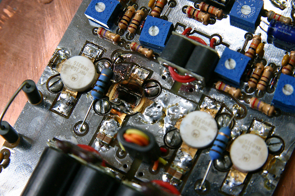
| From the picture of your board, the \"L1 and L2 ferrite beads\" on the left and right sides of the board are shorting. These ferrite beads are conductive. If they touch the foil, they will short and cause your transistors to burn out. You need to put insulation under them. http://www.k6if.com/gallery2/main.php?g2_itemId=1851 |
| On: 07/12/11 8:08ac2cz said: |
| Yes, I agree its a problem with the kit. You can\'t see it in this photo, but I bent the wires so that the beads can not touch the ground foil. They are suspended just above the foil where the wire kinks. I have not had any problems since getting the amplifier working. |
Copyright 2001-2021 Chris Thompson
Send me an email