

This is the first high current power supply that I have built. All of my previous power supplies have been based on simple three terminal regulator ICs like the LM7812 or the LM317. That meant I was running my station from either a 12 Volt sealed lead acid battery or from a 1 - 30 Volt variable PSU I constructed from a cheap Radio Shack Transformer, about 10000uF of capacitance and an LM317, using the circuit shown on the first page of the datasheet for standard variable operation.
Both of these power sources had challenges:
I decided that my RF power amplifier would be based on a pair of IRF510s in push pull. This would need lots more current and would run best from 28V or more. My ideal power supply would therefore provide variable voltage from say 2V to 30V with something like 10A. I could then use it at 13.8V with a radio or operate a linear amplifier using 28V at 100 Watts output or more.
So I set out to build a better supply and started with an order to Mouser for a high current transformer Mouser 546-185G24. I could easily order a supply that delivers 10 or 20 amps at 13.8V, so I decided to build something different. If I could build a supply that delivers 28 volts at 7 amps, then I could drive an amplifier to nearly 100 watts, even if it is only 50% efficient. I would not be restricted to high cost 12 volt RF transistors. If I wanted to take the amplifier into the field, then I could use two sealed lead acid batteries, for a similar voltage.
I took inspiration for the design from the ARRL handbook, which described using pass transistors together with a three terminal regulator. I also added a transistor that would shut off the pass transistors once the current through a certain resistor (R4) was above a certain level. Once the resistor is dropping more than 0.6V, then Q4 switches on and shorts out R1, which shorts the pass transistors from base to emitter and the turns them off. My initial calculations suggested that the 6A PNP TIP42 would make a good pass transistor. I would almost get away with 1, but designed the circuit with 2 to be safe..
But that turned out not to be the case. Building the supply turned out to be hard, because I did not understand Safe Operating Limts.
Figure 1: Variable Voltage Power Supply Circuit (with final modifications)

Test 1
Voltage started at 1V. Load is 0.5ohms from several power resistors. Current monitored through load with DVM on 10A range. 5A delivered to
load then the supply failed. The current sense transistor and one of the pass transistors were blown.
Test 2
To test I have put 0.2ohms as the current sense resistor (R4) so limiting will be at 3 amps. When tested it limits well at 2.5A.
Test 3
With R4=0.1ohm the current does not limit. As I turn up the voltage I can get up to 8A total, so there is 7A going through the pass transistors,
then sudden failure. The fuse is not blown. Smoke rises from one of the pass transistors. The heat through the test load has also melted the solder
between the resistors.
Why does it fail? I measured 0.6V was across the current limit transistor but it does not appear to hold back the current sufficiently. Why?
Test 4
With R4 (the current sense resistor) at 0.15ohms (using two 0.1ohm resistors in parallel and one in series) the current limits at 5.3A. Success!
It is very tempting to stop here. Especially since I just installed my last TIP42 transistor. (So far 5 have been destroyed) But why does the PSU only deliver 5.3A. The transformer is good for 7-8A. The transistors should be able to pass 12A.
Test 5
In the spirit of finding the limits by testing to destruction I soldered one more 0.1ohm resistor in parallel with R4, giving it a value
of 0.133ohms.
The current went briefly to 7A, then limited at 6.5A. It was steady for a few seconds then the PSU failed. Hmmm, why? Is all the current going through one pass transistor and not shared? The current sense transistor and the fuse survived.. But one of the pass transistors is short circuit, dead.
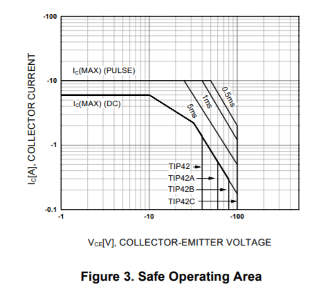 The TIP42 datasheet describes the safe operating limits for the transistor in Figure 3 on page 2. I had never
previously paid attention to these diagrams. Sure, I looked at the "Absolute Maximum Ratings" on the first page of the datasheet, but never
at this graph. It turns out that for this design, it was critical I understand this graph.
The TIP42 datasheet describes the safe operating limits for the transistor in Figure 3 on page 2. I had never
previously paid attention to these diagrams. Sure, I looked at the "Absolute Maximum Ratings" on the first page of the datasheet, but never
at this graph. It turns out that for this design, it was critical I understand this graph.
You can study the chart, but bascially the summary is this. The TIP42 is only good for 6A when the collector-emitter voltage is 10V or less. I have designed a variable voltage PSU, and the emitter is typically at 34V. In an effort to keep the test manageable, I was using low voltages and low value resistors. I reasoned that this was "less power" and should be a good initial test. That put the collector of the TIP42s at perhaps 4-10V. So I had 20-30V from collector to emitter. If you relook at the Safe Operating Limits graph then you can see the problem. The transistor will fail at about 2.5A with 30V across it.
So I had a problem. I needed a TIP42 that will handle 6A with 30Vce. But one does not exist...
The answer is to add more pass transistors, or to not use a variable supply. If I had designed this solely as a 30V PSU, then it would not have been an issue. I wanted to keep the variable supply, so the PSU now has 3 pass transistors, even though I thought from my initial calculations that 2 was probablly overkill.
I learnt a lot building this supply, but like most of my electronics projects, the learning is far from over.
The supply now works, but it is not perfect. It should limit if the supply is short circuited, but it does not seem to react fast enough and a pass transistor fails. I need to address that.
The supply does not have an over-voltage protection circuit. If one of the pass transistors fails then typically the supply jumps to 34V. That could destroy the circuit that it is connected to. Designing an over voltage circuit for a fixed output supply is relatively straightforward and uses a crowbar circuit. Designing one for a variable supply is not easy though, and I am working through ideas..
Copyright 2001-2021 Chris Thompson
Send me an email