
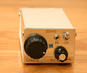
I started building this radio for the wrong reason. At first I wanted something to test the Gateway40, an SSB tranceiver that I was building. I only had a direct conversion receiver, so it was impossible to see if I had supressed the oppostite sideband correctly. I was scratching my head, trying to determine the best way to test it, and I decided to build another single signal receiver.
It turns out that it is tricky to build any single signal receiver. It was not the best or easiest way to test my transmitter. In the end I built one of the KB9YIG Softrock 40 Software Defined Radio Kits as a test instrument. That worked well because I could see both sidebands on the computer display. After some mental gymnastics to work out which side band was which, it was then simple to adjust.
I had already built most of this simple superhet though. So once the Gateway40 was working, I finished this as a companion receiver to the "First Transmitter". Which was another side project I built to understand why the Gateway40 transmit power chain was not functioning. But that is a another tale.
This receiver is based on a design by Rick Campbell KK7B which he posted to the EMRFD Yahoo Group, called the Compact Superhet. I had cheap 11MHz computer crystals from Mouser though, so I had to make a set of updates for the different frequencies involved.
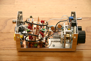
The Simple Superhet is built into a Radio Shack Aluminum Project Enclosure. I love these little boxes. They are so cheap ($2-$3 in 2010). They are a great size. Easy to machine. Always available in their stores. This is the same box that I built the First Transmitter into, so they match, I guess.
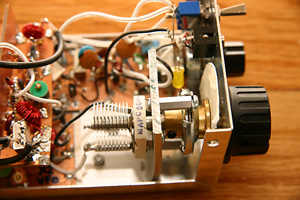
The VFO board is under the front end/IF board. I mounted the capacitor on a bent piece of aluminium that I made from a strip purchased at The Home Depot. It was a strip about a meter long (3') and about 4cm wide (1.5"). I also mounted the Jackson Brothers reduction drive on the bracket. This is a different approach to the Gateway40 and seems to work better. There is no change in frequency if the box is picked up or the case is flexed.
Adding a reduction drive always makes it difficult to see which frequency I am on, so I mounted a cardboard disk to the reduction drive
and wrote the frequency on it at intervals of 50KHz. The frequency is then visible through a small hole on the front panel.
VFO Capacitor and Reduction drive.
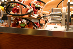
The front end and the IF strip are mounted on the same board, with a shield between them. The sheild is probablly ineffective. It did not seem to make a difference when I added it
This was not one of those projects that "just worked" once I connected it all together. It gave me some trouble, so I tested it one module at a time, using my HP signal generator (that I bought on ebay.com) and the RF Power Meter described in EMRFD. I don't currently have an oscilloscope, at least not one that works well. This meant that each module was fed with a low level input and I measured the response into the 50ohm test meter. When all of the modules were working I reconnected them together and tested the whole receiver. There were no problems once the individual modules were working.
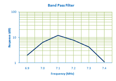
The front end band pass filter is lousy, as can be seen in the chart. At first I thought that was going to be a problem, until I
realized that the band pass filter is part of a tuned front end. When I measured the response of the front end, I realized that it
gives a very sharp response, with a 3dB bandwidth of only 200KHz.
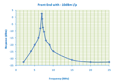
The front end initially peaked at 6.92MHz, which was near enough to my design frequency of 7.05MHz, but would not allow me to tune higher
in the band. I also found that the
trimmer capacitor was at minumum capacitance, so I likely did not have the maximum gain. I adjusted the capacitance in parallel
with the trimmer so that it peaked in the middle of its range when fed with a 7.05MHz signal. The front end has 10dB of gain.
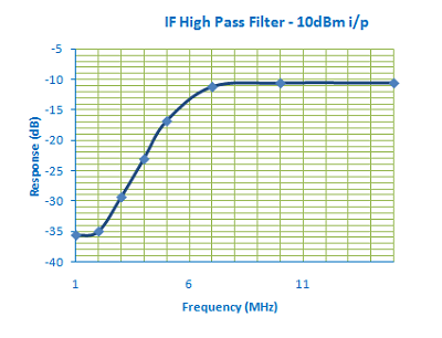
My IF is 11MHz, so I need to up-convert the incoming RF, rather than down convert. So I replaced the LPF on the input of the IF for a High Pass Filter, with a cutoff frequency of 10MHz. This means that the IF strip is only amplyfying frequencies in the range we want, minimizing noise. The crystal filter will supply the selectivity.
I designed the HPF with ELSIE and it tested in line with the design, as can be seen from the chart below. The image response at 3MHz is suppressed 20dB.
 I tested the IF strip without the crystal filter and quickly determined that it had negative gain. Not what I was after. Then
I realized that I had not changed the component values in the tuned ciruit for the new IF frequency. A quick check with the
calculator using f= 1/(2*Pi*sqrt(L*C)) showed that the components values were not resonant at 10.98MHz - the actual frquency of the
crystals. Given my capacitance of 30pF plus 10pF for the
center of the trimmer, and solving for L=25330/f*f*C (where C is in pF), we get L=4.287uF. Using my toroid spreadsheet, that gave
33 turns on a T37-2. I fiddled with the components and fed the IF strip from the signal generator, until I could peak it nicely
with the trimmer capacitor
Finally I played with the beat frequency oscillator, to make sure that it would be on the correct side of the crystal filter. CW and SSB on 40M are both received on the lower sideband, so the BFO needed to be about 600Hz above 10.98Mhz.
Once each of the stages were working, I connected them all together and quickly managed to receive signals. It is quite responsive, with a narrow bandwidth that works well for CW. It is a bit too narrow for SSB, but works in a pinch.
Copyright 2001-2021 Chris Thompson
Send me an email